
Lesson 6 -Intro to DC Circuits

In this lesson, we will discuss what are Direct Current (DC) “Circuits,” and how they are used. We will learn how to draw various schematic symbols that make it easier to design, understand, and troubleshoot problems.
Let’s start with some electrical components and learn how to draw their schematic symbols.
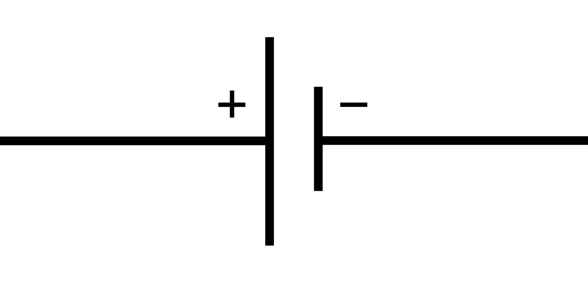
Batteries: We learned this symbol in lesson 5. Notice how the schematic symbol shows a negative and positive side just as all batteries have.
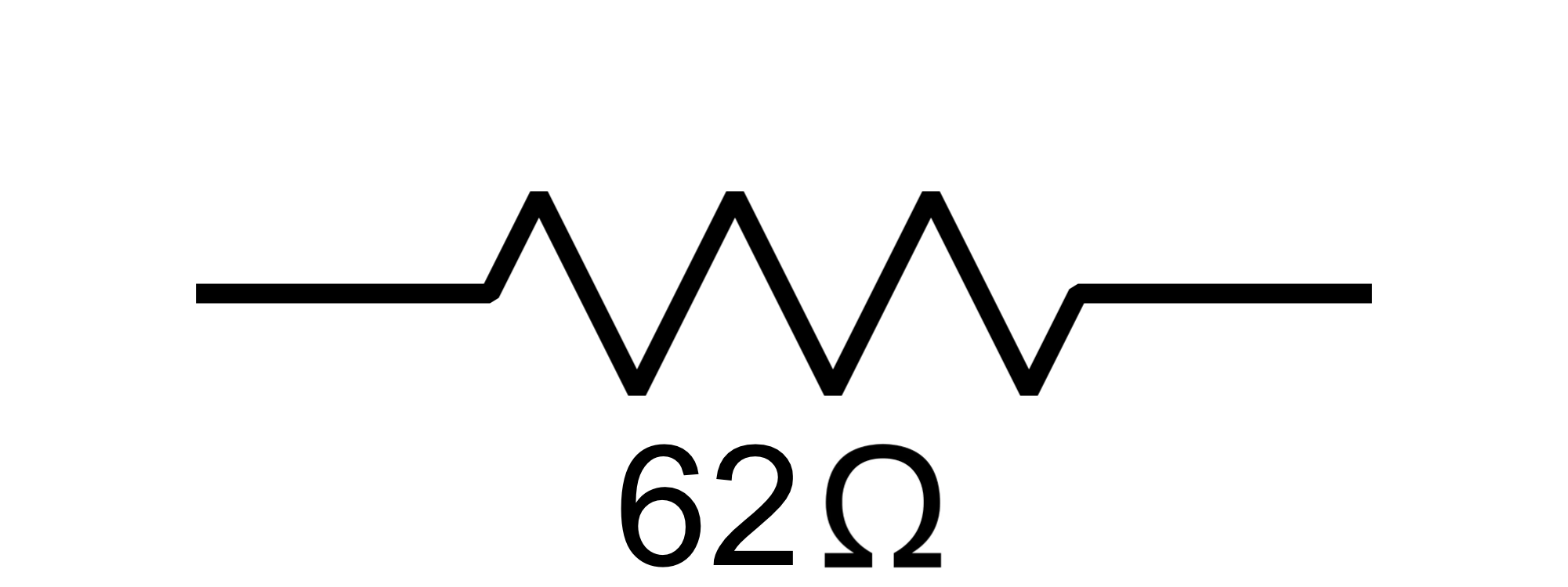
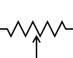
Resistors: The next symbol is that of a resistor. Resistors oppose the flow of current in a circuit.
If you remember working with Ohms Law in Lesson three, by changing the resistance in a circuit, you will change the Voltage or the Current as well, in order to achieve the desired levels that you are looking for.
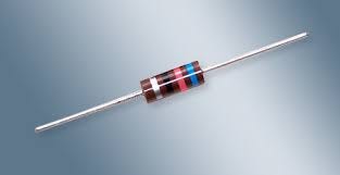
The standard carbon composition resistor below, is used in circuits in order to achieve the desired levels of voltage and current in a particular circuit.
Their values are in ohms. They use a color code printed on the resistor to identify their number of ohms they resist.
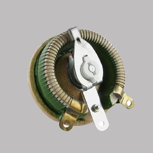
The volume control on your radio is a variable resistor. Many times it is made of wound wires and a slider. As you move the slider you connect more or less wires which varies the resistance. These variable resistors are sometimes called potentiometers.
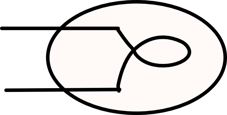
Another resistor is the wire inside of traditional light bulbs, automotive lamps, and flashlight bulbs. The wire is usually made of tungsten and has a high resistance. When current flows through the tungsten wire, it gets hot, glows, and makes light.
LED Lights work differently. We will discuss them later.
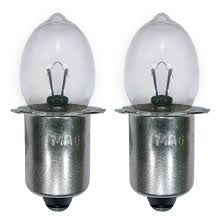
Lamp OFF and Lamp ON
Switches
There are many types of switches. We will limit our discussion at this time to what is called a Single Pole, Single Throw Toggle Switches. (SPST), Single Pole, Double Throw (SPDT) and Push Button Switches.
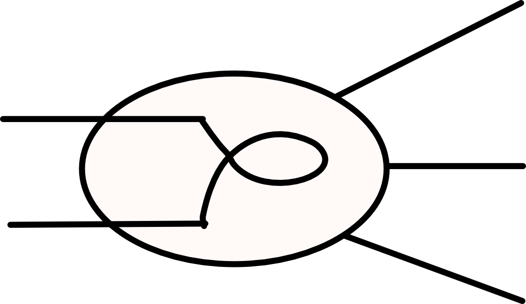
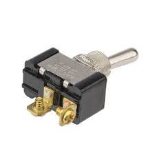
Switches Single Pole Single Throw / Toggle Switch
For switching a single conductor / single circuit path on or off by “throwing the toggle.”
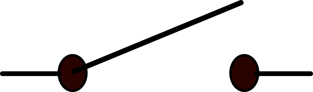
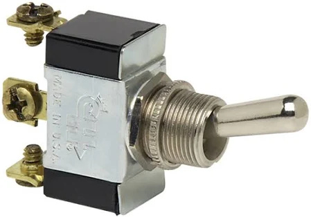
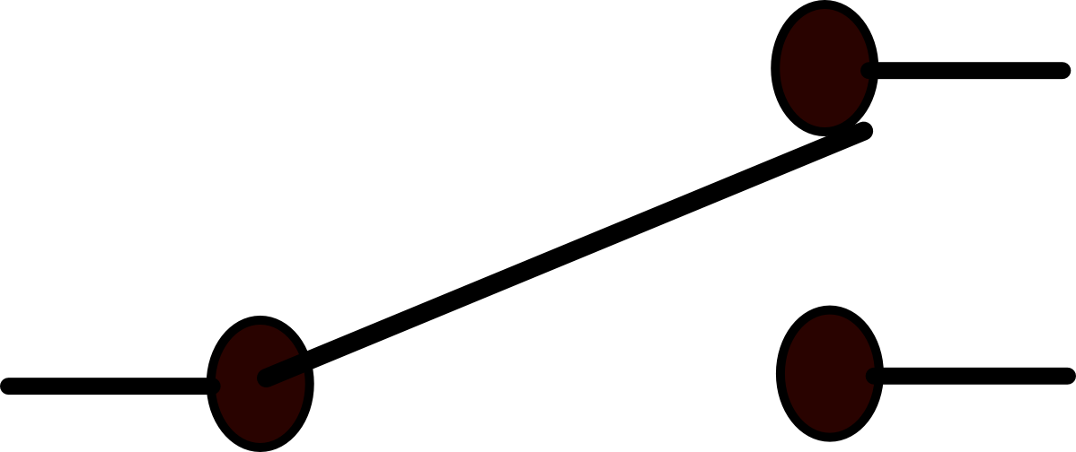
Single Pole Double throw Toggle Switch
This type of switch can be used to switch one circuit off while switching the other circuit on at the same time. The center part is the common which may connect to a voltage. In this case the upper right connection is the normally closed side, (NC) and the bottom right is called the normally open side. (NO). NC/NO/Common will be stenciled onto the switches.
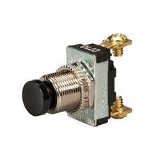
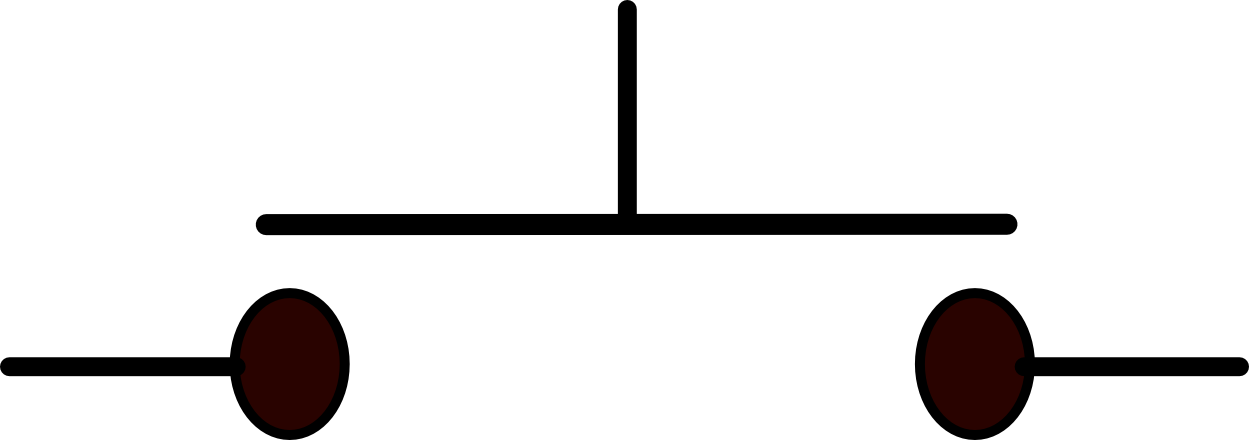
Push Button Switch, Normally OFF until pushed. This is used to momentarily turn something on or send a pulse of voltage to a circuit, like a reset switch on a computer
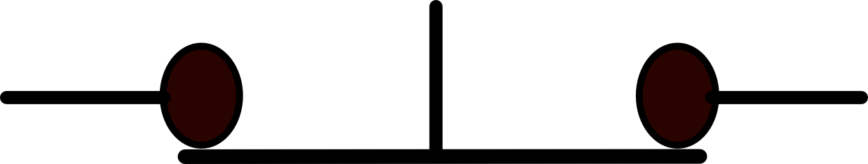
Push Button Switch Normally ON until pushed
You should practice drawing the schematic symbols above and know what they are and have a basic idea of how they are used.
————————————————————————-
OUR FIRST CIRCUIT… Your Grandpa’s Flashlight, (not an LED).
Now, time for the fun part. We will “dissect” a flashlight. Scalpel please!
Below, we can take a peek at the insides of typical flashlight using 2 -D Batteries, an tungsten light bulb, and a switch.
Schematic diagrams make it easy to understand and draw electric and electronic circuits. as well as trace circuits and troubleshoot problems.
The most important thing you can take away from this lesson is:
IN ORDER FOR CURRENT TO FLOW IN AN ELECTRICAL OR ELECTRONIC
CIRCUIT, IT MUST HAVE A COMPLETE PATH.
Any break, or disruption in that path will stop all current from flowing. Nothing -Nada - Zilch - KaPut!!!
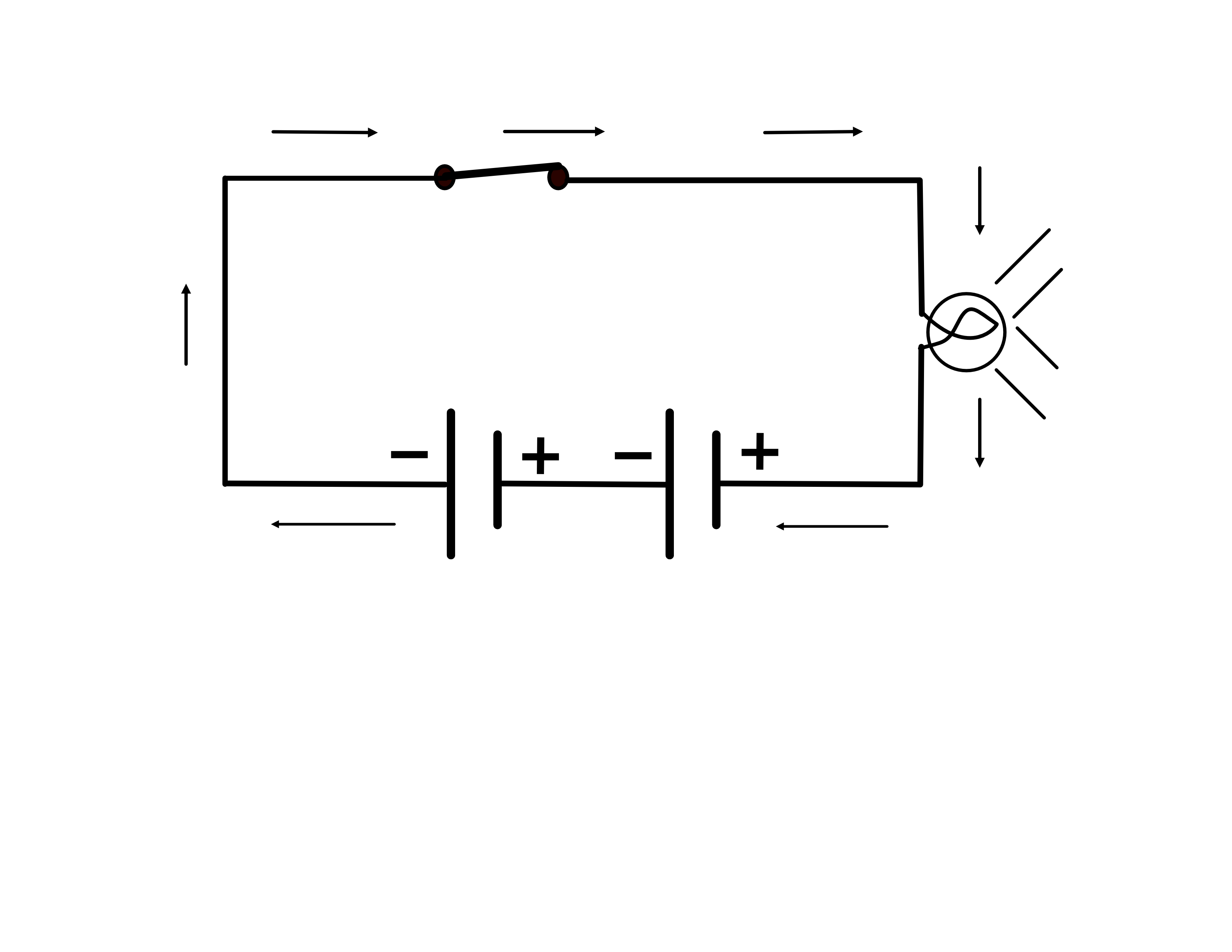
The drawing and schematic below shows the same flashlight with the switch closed.
Closing the switch, completes the circuit path. Let there be Light.
TROUBLESHOOTING: Possible circumstances that would break the path and cause the lamp not to come on are: The switch is open or faulty. The batteries aren’t making a good connection due to corrosion or dirt. The tiny element inside the lamp is burned out. The batteries are run down and not producing any or enough voltage. The housing is defective, warped or broken and not holding the components properly.

Note the arrows in the above schematic. They represent how the electricity flows.
Starting with the negative side of the left battery, current flows through the conductors, through the switch, through the lamp and back to the posistive side of the batteries.
Since the two 1.5 volt batteries are connected in series, for a total of 3 Volts, You can think of them as one 3 Volt battery.
Note: The bulb uses a high resistance element, and the battery terminals, connections, conductors, and switches are close to zero ohms, which is little or no resistance..
When the current tries to flow through the lamp, it is opposed by the high resistance, of the lamp’s element, which causes the lamp to heat up, and produce light.
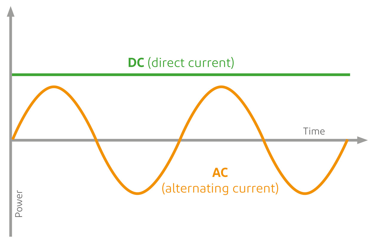
If we graph someone turning a flashlight on and off over time, this is what a DC Timing diagram would look like.
Now let’s compare the DC graph to an AC graph.
This concludes the introduction to Circuits. You should be able to recognize and draw these schematic symbols, know what they are and how they work, and draw a schematic of your grandpa’s, non-LED flashlight.
If you can do this, you have come a long way.
In the next lesson we will talk about AC.